1. INTRODUCTION
The Tous dam is located in the province of Valencia, approximately 40 km from the Levant Coast, on the Júcar River. It received this name because it has been built on the same site of the dam that, on October 20, 1982, underwent the consequences of a disastrous flood, with an estimated 11,000 m3/s at its peak, and registering a hydrograph in the dam of a volume about 600 hm3. This hydrogram has been associated with 500 years flood. The peak rainfall recorded surpassed 1,000 mm.
This flood, which overflowed the crest of the dam, originally projected in two stages and which was, at that moment, in the final stage of the first phase of construction, eroded the middle body of clay and rockfill, and caused considerable damage to the vast agricultural plains located downstream from the dam.
Some of the elements from the earlier dam were used for the new construction: concrete blocks from the sides, the bottom outlet, together with the lower part of the core belonging to the previous dam that had not been damaged by the flood, and which now forms part of the new core (fig. 1).
The project offered a solution for a heterogeneous earth dam, with a middle body of clay and rockfill, 133.5 m high (109 m above the river bed). The volume of the reservoir at the Normal Maximum Reservoir elevation is 340 hm3, although between this level (elevation 130.00) and the crest (elevation 162.50), the reservoir may still store 400 hm3, in contrast with the 100 hm3 of capacity of the former dam (crest of the first stage) (fig. 2).
The two level ungated spillway is capable for a projected volume of flow of 5,200 m3/s, at elevation 145, though its maximum capacity is almost 20,000 m3/s. Nevertheless, an initial control of floods is the mission of the dam's intermediate outlet, which for reservoir elevation of 130, that is, before the spillway begins to discharge, is capable of voiding around 1,200 m3/s (fig. 3).
As to the site of the dam, after numerous studies and researches, due mainly to topographical problems and the impermeability of the foundation, any other possible alternative locations at a distance from the former site were discarded. Its final location, with the axis of the dam 60 m downstream from the old dam, also allows for the utilization or adaptation of a large part of the structures that went undamaged in the 1982 flood: the diversion tunnel, the bottom outlet, the inspection galleries and the grout curtains. Part of the old spillway, unaffected by the inundation, is also used as foundation for the intermediate outlet of the new dam.
The importance of the work, together with the special problem posed by the fact that it is constructed above the remains of the earlier works, especially where the behavior of the core and its contact with the concrete blocks at the sides are concerned, made it necessary to carry out more intensive monitoring than is normally necessary for similar dams. This instrumentation was also applied to the adjoining structures: the intermediate outlet, the bridge over the spillway, etc (fig. 4).
2. THE INTERMEDIATE OUTLET
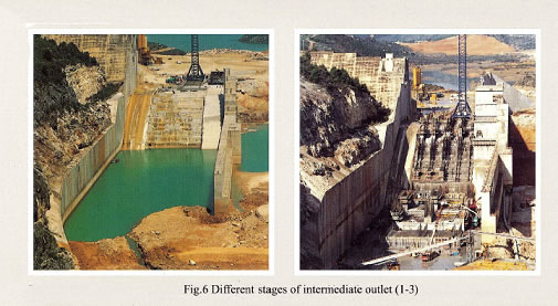
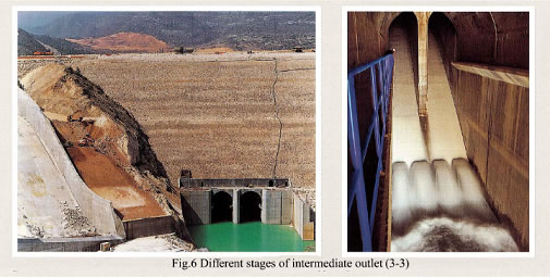
It is made up of four pressure ducts, 5 m x 4 m (width x height) of interior section, with two closures for each duct, the first one, a down-folding "Bureau" gate, 3.5 m x 3.5 m, and another one downstream, a Taintor gate 3.5 m x 3.0 m (fig 5). The discharge is in free flow to 4 ducts, 5.0 m wide and with a varying height, until it reaches the hydraulic jump energy dissipater, where it enters two single ducts of a rectangular vaulted section, 11.5 m wide by 24 m high, built over the stilling basin of the spillway of the old darn. The slope of the outlet adapts partially to the structure of the former spillway, though it was necessary to raze in steps the existing sill, in the depth and width necessary in order to lay the foundation of the new structures (fig. 6), and executing the final slope according the conclusions of the hydraulic model.
The control chamber has not undergone modifications as to its former position, but it has in its distribution and interior geometry, mainly motivated by the new accesses and by the ventilation system of the projected "Taintor" gates.
The main access, in the original project, was through a tower designed as well for the ventilation of the valve chamber. It was located just upstream from the middle body of the dam, adjacent to the chamber, thus embedded in the body of the dam approximately in its lower two thirds.
The lowest zone formed a body with the caisson chamber, founded upon the concrete of the old spillway. The shaft was of a rectangular section, 16.00 m x 7.75 m in its lower part, and 11.25 m x 6.75 m in the upper part, incorporating within the well for the staircase and the elevator, as well as a large duct of 11.5 m with an exterior outlet, for the ventilation of the Taintor gates.
The control chamber of the intermediate outlet of the Tous dam is equipped with three accesses. Not in vain may we consider it to he the neuralgic centre of the dam: the first access, proceeding from the network of galleries of the old dam along the right river bank; another access on the left side, existing on to a platform downstream from the intermediate outlet; and the main access through a tower that rises up to the crest, tangent to the latter on the downstream edge. The entrance to the chamber from the lower part of the tower is executed through a gallery on the right bank, through a solid structure of rolled compacted concrete, filling the existing space between the old spillway and the concrete structure of the outlet.
In this same rollcrete structure, at a lower level, its last span resting upon the grade line of the old spillway, and on the vertical grade of the gallery, a 3.75 m diameter duct has been constructed, of prefabricated galvanized steel, for gates’ ventilation.
The final design of the tower is reflected in fig. 3. Its philosophy is based on eliminating the incompatibility in the deformations of a rigid structure, immersed in a body with the deformability of the rockfill of the dam. The result of this contradiction gave rise to a flexible structure, made up of modules or independent rings of reinforced concrete, with an interior diameter of 4.50m, and separated vertically. Its interior distribution allows for space for a winding staircase and an elevator. In this way, each ring is supported by the surrounding rockfill, and the tower must only accompany the movement of the dam body, without constituting any type of impediment.
The modules measure 3.57 m in height, an interior circular section of 2.25 m of interior radius, and an exterior polygonal contour of 20 sides, with a variable thickness between 37.5 and 75 cm. Each module includes 21 stair steps, 70 cm wide and 17 cm of riser, alternatively interrupted by a landing, 70 cm wide, or 105 cm in the landings where the elevator stops (fig. 7).
The stairway is conceived as a structure solidary to the ring, so that the stringboard, a spiral design, is built into the shaft of the ring, also incorporating the concrete steps. Each ring, in addition, includes its corresponding landing, solidary and constructed at the same time as the rest of the base structure.
The total weight of the complete module is around 100 tons.
The structure of the tower materializes through the construction upon a solid foundation, using a special foundation module, with an octagonal section, built in situ, which incorporates the entrance to the access gallery to the caisson chamber; 18 prefabricated modules, and an upper structure, resting upon the body of the dam, independent of the lower ring, which will eventually house the machinery chamber of the elevator, The hypothesis that the tower moves and becomes deformed in solidarity with the dam body implies that to measure its elements, it is necessary to be sufficiently acquainted with the stresses and deformations in the dam materials surrounding the tower.
In addition to the measures already described, aimed at absorbing the movements between modules, the following measures were adopted for construction:
– Interposition of a flexible element, guaranteeing the sealing between consecutive modules, preventing a transfer of loads to the immediately lower one. After the first constructive experiments, a system was adopted, employing flexible sheets of Polyethylene, affixed to both sides of the joint with epoxy resin mortar, protected by galvanized sheet metal.
– Three grooves for the installation of jacks, on each side of the joint between adjacent modules. The dimensions adopted were 0.25 m x 0.25 m in ground plan and 0.275 m high, capable of accommodating a jack with a capacity of 100 tons. Its mission is to support the modules situated above it, until the pressure of the surrounding clam material allows for its removal.
– Provisional safety bumpers in case of an unexpected settlement, once the jacks have been removed. At the moment, 3 pairs of equidistant metal plates, with a total thickness of 4 cm per pair, are being employed.
3. MONITORING AND AUTOMATIC DATA COLLECTION CENTRAL SYSTEM
The automatic data collecting system enables the user to read the following sensors:
114 Vibrating wire piezometers
82 Vibrating wire pressure cells.
14 Soil extensometers.
44 Relative movement extensometers.
34 Rod extensometers.
161 Vibrating wire reinforcement strain gauges.
29 Platinum thermo-resistance (thermometer).
3 Vibrating wire gauges for measuring seepage.
• Storage level.
• Opening and closing degree of the bottom and intermediate outlets and intake.
• Opening and closing of the intermediate outlet and intake,
• Discharge measurements and the level in the control tank.
• Measured levels and discharges downstream from the dam.
• Accelerometry network.
• Microseismicity network.
10 data collecting stations were installed for the purpose of telemeasuring the sensors located in the dam. Each of these stations has a capacity for reading 64 sensors and they are located in 9 of the dam galleries. The tenth one is outside the dam in the downstream berm level 130.
The collecting program, which has been specifically designed for monitoring, has the following basic characteristics:
• Multi-task operating system.
• C programming language.
• "Windows" and icons type interface with the user.
• Potential for connecting alphanumerical terminals.
• Potential for enlargement for local network operation.
• Detecting and transferring readings in the memories of the automatic data collecting stations.
• Automatic reading frequency change in case of predetermined alarm levels triggered.
The program contains the following modules:
• Module for managing the configuration and operating parameters.
• Reading acquisition module.
• Module for presenting graphic and numerical reports:
- Alarms
- Tables
- Time graphs
- Graphs showing the correlation between two sensors
The dam computer is connected via modem to other one placed at Júcar Hydrographic Confederation headquarter offices. From this one any reading from everysensor connected to any of the data collecting stations could be easily taken.
4. SUMMARY
Main singularities of the Tous dam have been described: the intermediate outlet (huge discharge capacity; stilling basin inside dam, founded over rolled compacted concrete in the spillway of the old dam; and, the access tower to control chamber) and automatic data collecting system from instrumentation.
The access tower to the valve chamber of the intermediate outlet of the Tous darn is more than 80 m high construction. The project modifies the design and location of the previous structure, with a tower tangent to the crest of the dam on the downstream edge, to avoid contact with the reservoir. The tower is built of independent rings which move with the rockfill of the dam body. After an analysis of the expected movements of the earth fill at the axis of the tower, a horizontal camber has been adopted, permitting the tower to compensate in the future the greater part of its deformation and approach the vertical. The independence between rings is assured by leaving sufficient room between the opposite surfaces of the rings in each joint. All the rest is left to the pressure exerted by the rockfill, causing the structure to "float" in its.
The Tous dam, which was constructed over the remains of an older dam, posed a problem that required the installation of a more extensive and complex monitoring system than is normally required for dams with similar characteristics. The instrumentation installed for the dam and the use of a data collecting system that has made it possible to increase the efficiency of the monitoring process and to check the dam behavior.
5. REFERENCES
[1] UTRILLAS, J. L., GAMO, A., SORIANO, A., 1992 : " Reconstruction of the Tous Dam ", Water Power and Dam Construction, Sept. 1992.
[2] UTRILLAS, J.L., SANTA A., 1994: “Access tower to the intermediate outlet of the new Tous dam”, Eighteenth Congress on large dams, Q.70 - R.23. Durban
[3] UTRILLAS, J.L., SAMPEDRO, J.M., 2000: “Instrumentation or Tous dam”, Twentieth Congress on large dams, Q.78 - R.54. Beijing
6. FIGURES
1. General view of remains of earlier dam
2. General view of Tous dam
3. Intermediate outlet
4. Different stages of construction work’s
5. Bureau and Taintor gates of intermediate outlet
6. Different stages of intermediate outlet
7. Detail of access tower’s modules