1. INTRODUCTION
The Irape Hydroelectric Power Plant is owned by Cemig Geração e Transmissão S.A., is located in the Jequitinhonha river, between municipalities of Berilo and Grão Mogol - Northeast of Minas Gerais State, Brazil.
The first studies of river basin Jequitinhonha were developed in the 60s by Canadian consulting company - CANAMBRA Engineering Consultants Limited, has started his studies in Cemig inventory in 1984 through the company Enerconsult Engenharia Ltda. The feasibility studies were completed in 1993 and the basic project was developed between 1998 and 1999. In February 2002 started the construction of the project by the Consortium of Brazilian Companies formed by Construtora Andrade Gutierrez, Construtora Norberto Odebrecht, Ivaí Construtora de Obras, Hochtief Int. do Brasil, for construction works; Voith-Siemens Hydro for the equipment; as well as Intertechne Consultores Associados and Leme Engenharia for the engineering design.
This is a large undertaking, presenting a rockfill dam with clay core and maximum height of 208 m - the highest in Brazil (Figure 2), located in a place of very rugged topography, the type canyon with difficulties constructive associated with topographical aspects and local geochemical conditions.
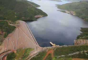
Figure 2 - View of Irape Dam.
The plant is in operation since July 20, 2006, with installed capacity of 399 MW to produce 1,807,188 MWh per year of firm energy.
2. PROJECT LAYOUT
Figures 3 e 4 shows the layout of the main structures. Main features are:
Figure 3 - General Lay-out.
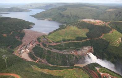
Figure 4 - Picture of the General Lay-out.
- Two 14m-diameter diversion tunnels, the lower one with an underground control structure accessed by a shaft and a length of 1227 m, and the upper one uncontrolled with a length of 1067 m.
- A rockfill dam with clay and gravel core, 208-m high and volume of 10.300.000 m³ (Figure 5);
- Two 12m-diameter spillway tunnels with external structures for controlling gates (discharge capacity of 4000 m3/s), and two underground chutes, 634 m long, discharging into the river issuing from a flip bucket located 70 m above the stilling basin (Figures 6 and 7);
- One emergency mid-height outlet, with a structure for radial gates, 2.000 m3/s discharge capacity, also with an underground chute;
- A power plant with three power tunnels, an external powerhouse for three Francis turbines.
Figure 5 - Rockfill Dam Typical Sections
3. PROJECT CONDITIONING FACTORS
The Project conditioning factors resulted chiefly from the topographic and geologic characteristics of the site, and of course from the requirement of a 40-month schedule for initial energy generation and the costs limitation to render the project economically viable. The main controlling feature was the necessity to adjust design of structures and construction activities to the well-defined seasonality of the river.
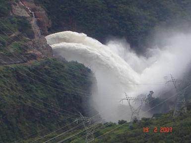
Figure 7 - Picture of the output the Spillway.
4. Topography
The region has a flat erosion surface deeply entrenched by river erosion. At the site the result was a narrow canyon with almost vertical side walls, about 80 - 100 m wide and 80 m deep, a narrow flat bottom and an additional river channel about 30 m deep and 20 m wide (Figure 8). The name IR-A-PÉ, (“going on foot” in Portuguese) so it goes, comes from the fact that the only way to get to the bottom of the valley was by walking down the steep slopes.
Figure 8 - Valley cross-section through the clay core and concrete block.
The topographical configuration caused serious problems of access, large volumes of excavation under very difficult conditions as well as problems for stockpiling and re-handling construction material. The 208-m high dam with a very tight construction schedule in a very narrow valley with steep abutments generated problems to reach, trim, clean and treat the foundations, to place and compact a complex zoning of different materials and involved design and construction care to minimize arching effects.
5. Geology
The site has a bedrock of hard quartz mica schists, with good foundation and excavation conditions, for both surface and underground work, when fresh. Topsoil is moderate to thin, but the zone of weathered rock is usually thick and irregular. Sub-vertical stress relief joints with soil-like infillings affected the excavations to the sound rock surface under the dam core.
The main geological characteristic, however, was the occurrence of sulfides in the rock - chiefly pyrite and pyrrhotite in percentages higher then normal and that affected the initial studies. A realistic assessment of the seriousness of the issue involved studies carried out by CEMIG, the concrete laboratory of Furnas, the University of Minas Gerais and a special Board of Consultants on Concrete Deterioration defined how to cope with the problem, but the adoption of unusual design and construction care was still necessary.
6. DAM - DESIGN AND CONSTRUCTION
The dam is a rockfill structure with a earth core. Its maximum section is shown in Figure 5, which also shows the complex zoning, the materials used and the concrete block built at the bottom of the lower channel. The main factors that conditioned and presided over the final design were:
- canyon-like topography of the valley;
- effects of the sulfides;
- materials available;
- very tight construction schedule.
In the region of the dam the valley has a flat erosion surface deeply carved by the river erosion. This resulted in a narrow canyon with almost vertical side walls, about 80 - 100 m wide and 80 m deep, a narrow flat bottom and an additional river channel about 30 m deep and 20 m wide (Figure 8).
The valley shape, besides creating obvious difficulties to access its lower portion to treat the foundation and place and compact the initial rockfill, posed two main factors: (1) the occurrence of earth or laterite-infilled sub-vertical stress-relief joints that required deep excavation to reach sound rock, and (2) the serious arching effects in the dam core eventually produced by the narrowness of the valley. Figure 9 depicts a cross section of the valley along the centre-line of the cut-off excavated to sound rock under the impervious core. It shows the original topography and the trimming of the core foundation required to eliminate the stress-relief joints and minimize arching problems. It also shows the concrete block built to help expedite construction work out of the deep channel and also to reduce arching effect.
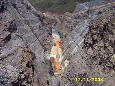
Figure 9 - Picture of the excavated canyon in the region of the clay core.
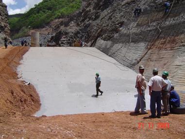
Figure 10 - Picture of concrete block surface showing waterproofing membrane.
The presence of sulfides and aggressive waters also affected the design and construction features of the dam. The presence of sulfides in the rockfill materials were not considered as damaging due to the lack of oxygen in the water needed to produce expansive minerals and disintegration effects. Most of the water coming from the reservoir will have a low average amount of sulfates and only the concentration of these materials at the bottom of the reservoir, at the upstream toe of the dam has to be considered. Thus, the concrete block built at the bottom of the channel had to be protected against the aggressive waters, and this had to be considered when treating with dental concrete the irregularities of the foundation. The concrete block under the core was only moderately extent, but was improved at the bottom to reduce the seepage of aggressive waters through the foundation. Along with the adoption of measures related to the composition of the concrete, like the use of ultrafine sulphate resistant cement with low W/C ratios and microsilica, the concrete block surfaces were waterproofed to avoid contact of the aggressive water, using an epoxy-based membrane (Figure 10).
An additional problem was the lack of adequate materials in quantity and quality consistent with the design requirements. Figure 5 shows the complex zoning adopted to maximize the use of the material from the required excavation and nearby deposits. For the rockfill, after extensive investigation and analyses the use of sulfide rock in various weathering, states was allowed. Non-sulfide rocks from a quarry located at about 5 km away from the dam were limited to drain, filters, transition materials and some external slopes such as the upstream shell, in the reservoir fluctuation level zone, and in a protection layer on the downstream slope. As shown in Figure 5, 3B core material is a gravel-earth used up to elevation 407.0 m to increase its deformation modulus. The lack of proper materials made it necessary to mix sandy-clayey soils from near-by deposits and gravely materials in a soil batching plant.
The dam core was built with sandy-clay with the precaution to use a mixture of gravel and clay in the deep channels, to get higher rigidity modulus in this zone [1], [2] and [3]. A layer of more plastic, self-healing soil was placed along the clay/rock contact on the valley walls to help the redistribution of stresses.
Natural sand was used in the fine filters, and crushed rock in the coarse filters and transitions. Based on what was observed in the finer fractions of the sulfide-rich rock excavated from the exploratory addict, only non-sulfide or sulfide-poor rocks were used in the transitions, brought from the quarry for concrete aggregate.
The tight construction schedule and the strict economic limitations of the job, made obligatory the use of the excavated materials in the dam embankment, including large amounts of weathered sulfide-rich rocks. Consequently, with the exception of materials 7 and 9, which were made of non-sulfide or sulfide-poor rocks, all the other embankment materials came from the required excavations.
This was decided after carrying out several experimental fills and investigating the rockfill deposits of different ages, as well as the water seeping through the rock mass or the weathered wastes and embankments. See figure 5 concerning the following comments.
Material type 6 is made up of sound or slightly weathered, sulfide-rich rocks and was placed in 0,80 m thick layers. The amount and type of sulfides had to considered in the use and positioning of this and other rockfill materials, taking into account the possible generation of acid effluents, able to concentrate in the bottom of the reservoir or seep downstream. For this reason, this material was used in the upstream shell, below El. 470,00, in the zone to remain permanently underwater, in a reducing medium, poor in oxygen and not able to affect the primary rock sulfides and produce excessive amounts of acids.
Material 5L, placed between the upstream shell and the clay core, is an unconventional type of material - a saprolite with decomposed rock fragments, well graded, CU around 140 to 160, void ratio of 0.26 to 0.31 (for a rock density of 27kN/m³), which yielded, by compaction, very high deformability moduli and very low permeabilities. The amount of sulfides was limited to 0,1%, a requirement that implied detailed control of the stock-piles and the liberation of its use based on collecting and testing numerous samples. Being of very low permeability, this material acted as well as an upstream enlargement of the clay core. Material 2A, used immediately upstream of the core, is a fine sandy-silty residue of the crushing of sulfide-poor rocks, of low cost, used to clog occasional fractures in the clay core.
Materials 5 and 5A are, respectively, slightly to medium weathered rockfill and medium to highly weathered rockfill, rich in fines and containing secondary sulfur minerals. The 5A material was placed downstream of the filters, between the 5 material and the outer shell of material 6. In test fills, those materials gave adequate mechanical parameters, with very low void rations, around 0,18 and quite high deformability moduli, near 80 MPa, but usually showed quite striking effects due to the sulfur oxides: yellow staining, efflorescence and heating. Since those materials were located downstream of the core, they were kept essentially dry. However, to reduce the amount of rain water seeping into this downstream zone, and prevent the production of acid effluents, a sort of “umbrella” was provided in the downstream slope, made up of 6 m wide sheets of HDPE (high density polyethylene), placed each 2,4 m in height, as shown in figures 10 and 11.
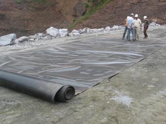
Figure 11 - Picture of HDPE (high density polyethylene).
To meet the very tight construction schedule, very high productions rates (up to 1.250.000 m³/ month of embankment materials) and some less usual construction procedures were required. For instance, to get to the height required to start reservoir impounding, El. 475.00, a downstream zone of varied width (min. 30 m) was left to be raised after this height was reached. Some additional cares were adopted during construction, as well, such has a zone of fine sand in the upstream face of the core, to help clog occasional seepage paths of aggressive waters trough core and foundation. Figure 12 shows downstream slope of Irape Dam.
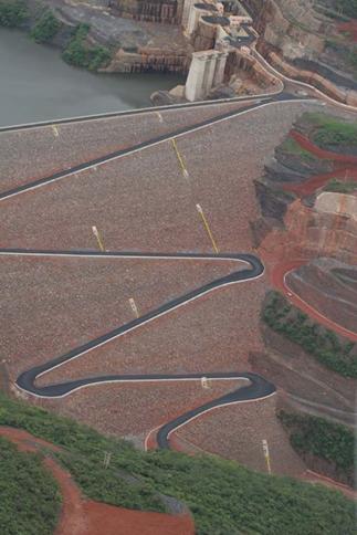
Figure 12 - Picture of downstream slope of Irape Dam.