Manwan
Hydropower Station
Introduction:
The Manwan Hydropower Station is located on the middle
reaches of the Lancang river in Yunnan Province, the People's Republic of China, and is the first completed large
hydropower station in the cascading hydropower development of the Lancang river. The
Lancang river is about 2,100km long, with a total drop of about 5,000m and a catchment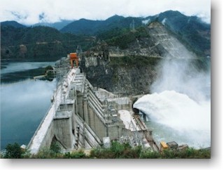 area of 174,000km2, of which 1,240km with a catchment area of
91,000km2 is in Yunnan Province. In accordance with the river development
planning two large reservoirs and eight cascade hydropower stations are to be constructed
on the middle reaches of the river. The Manwan Hydropower Station is the 6th
one and Xiaowan hydropower project will create a large reservoir on its upstream.
area of 174,000km2, of which 1,240km with a catchment area of
91,000km2 is in Yunnan Province. In accordance with the river development
planning two large reservoirs and eight cascade hydropower stations are to be constructed
on the middle reaches of the river. The Manwan Hydropower Station is the 6th
one and Xiaowan hydropower project will create a large reservoir on its upstream.
The catchment area at the Manwan dam site is 114,500km2. The Manwan reservoir
has a total storage capacity of 1,006 million m3 and an effective storage of
257 million m3. Its normal water level is 994.00m, with a corresponding storage
of 920 million m3. Its dead water levels are 982.00m and 988.00m before and
after the completion of the Xiaowan hydropower station respectively. Its dead storage is
663 million m3 before the completion of the Xiaowan Hydropower Station.
The main purpose of the Manwan hydropower project is to generate electricity. The project
which is classified as grade 1 in terms of its size and importance is constructed in two
phases. Its total installed capacity is 1,500MW including 1,250MW in the first phase and
250MW in the second phase. All five generating units in the first phase were put into
operation in June of 1995. An underground diversion type power station is to be
constructed on the right bank in the second phase, whose intake is arranged about 180m
upstream from the Manwan dam.
The commissioning of the Manwan Hydropower Station plays an important role in the
development of the national economy in Yunnan Province, development of the Lancang River,
implementation of the strategy of ransmitting electric power to other provinces and abroad
from Yunnan? as well as development of the electric power industry in Yunnan Province.
Main Project
Data:
The Manwan dam is of a concrete gravity structure with a straight axis at NE75o
55' 32.89". The dam, with its crest length of 418m at El.1,002.00m, is composed of 19
sections. The maximum dam height is 132m and the volume of the dam is 1,5484 million
m3.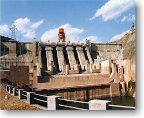
The flood releasing structure of the Manwan hydropower project consists of 5 crest
spillway , 2 low-level outlets and 1 tunnel spillway . The structure featured with
frequent operation, large discharge, high energy, long duration and energy dissipation by
river bend during the flood period. The crest spillway 1# through 5# are installed between
the sections 9# and 14#. The maximum discharge of each crest spillway is 2,405m3/s
(at the design flood level, the same below). The two low-level outlets, one long and
the other short, are located in the section 15#, with their maximum discharge of 2,436m3/s.
The tunnel spillway is arranged in the left bank , with a maximum discharge of
2,344m3/s. The five crest spillway and the left bank tunnel spillway
can be operated at 1/5, 2/5, 3/5, 4/5 openings and full opening separately. The two
low-level outlets can be operated at 1/2 and full openings respectively. The right bank
low-level sediment flushing outlet is placed in the dam section 8# with its inlet being at
El. 896.00m, while the left one in the dam section 14# with its inlet at El.
916.00m.
The water diversion system for power generation is installed inside the dam. The five
penstocks are connected with the scroll cases of the turbo-generator sets from No.6
through No.2. Each one is 97.449m in length and 7.5m in diameter. The power intake is
equipped with a 7.00mx11.5m bulkhead gate and a 7.00mx9.00m emergency gate, with its
bottom plate at El. 945.00m. The power discharge for each is 316m3/s.
The powerhouse accommodates five 250MW turbo-generator sets. All key equipment is made in
China. The rated head of the turbine is 89m. The type of the turbine is HL-231-LJ-550 and
that of the generator is SF250-48/12650. The design energy output of the power station is
6,200 GWh and 7,784GWh before and after the completion of the Xiaowan Hydropower Station
respectively. The total design installed capacity of the power station is 1,500MW. The
first generating unit was put into commissioning in June of 1993 and the other four in
June of 1995 in the first phase of the project.
Features of
the Project:
An overlapping type layout scheme is adopted for the
Manwan Hydropower Project, which consists of a concrete gravity dam, a powerhouse at dam
toe, 220kV and 500kV substations, a plunge pool and a left bank tunnel spillway . The
concrete gravity dam is connected with the powerhouse at dam toe. In order to improve the
stability of the dam and the powerhouse, the powerhouse is separated from the dam on the
top and jointed the dam at the bottom. A closed double-spanned slab-wall frame structure
was selected for both the powerhouse and the auxiliary plant. The plunge pool protects the
dam foundation and improves the high slope stability. The factors of large discharge
during the flood period and the narrow river channel at the dam site were considered in
the layout of the project complex.
Technical Data
for Manwan Hydropower Station
No. |
Description |
Unit |
Quantity |
No. |
Description |
Unit |
Quantity |
Ⅰ |
Hydrology |
|
|
|
Number and
size of the gates |
|
Working gate
5-13*20
Bulkhead gate 1-13*20 |
| |
Catchment
area at dam site |
104
km 2 |
11.45 |
2 . |
Left double
low-level outlet |
|
|
| |
Mean annual
runoff |
109
m 3 |
38.80 |
|
Floor
elevation of water inlet |
m |
|
| |
Average
annual discharge |
m 3/
s |
1230.0 |
|
Number and
size of the gates |
|
Working gate
2-5*8
Emergence gate 1-5*9.5 |
| |
Design flood
and discharge |
m 3/
s |
18500(p=0.1%) |
|
Method of
energy dissipation |
|
Curved filled
sloping bucket deflector |
| |
Check flood
and discharge |
m 3/
s |
22300(p=0.02%) |
3 . |
Right score
low-level outlet |
|
|
| |
Average
annual sediment load |
104 t |
4704 |
|
Floor
elevation of water inlet |
m |
|
Ⅱ |
Reservoir |
|
|
|
Number and
size of the gates |
|
Working gate
1-3.5*3.5
Emergence gate 1-5*6
Bulkhead gate 1-5*6.8 |
| |
Check flood
level (p=0.1%) |
m |
999.4 |
|
Method of
energy dissipation |
|
Curved filled
sloping bucket deflector |
| |
Design flood
level (p=0.02%) |
m |
994.0 |
4 . |
Left score
low-level outlet |
|
|
| |
Normal water
level |
m |
994.0 |
|
Floor
elevation of water inlet |
m |
|
| |
Limit water
level during flood period |
m |
985.0 |
|
Number and
size of the gates |
|
Working gate
1-3.5*3.5
Emergence gate 1-5*6
Bulkhead gate 1-5*6.8 |
| |
Initial dead
water level |
m |
982.0 |
|
Method of
energy dissipation |
|
Curved filled
sloping bucket deflector |
| |
Total storage
capacity (994.0) |
106
m 3 |
920 |
5 . |
Left-bank
spillway tunnel |
|
|
| |
Regulating
storage |
106
m 3 |
257 |
|
Floor
elevation of water inlet |
m |
964.86 |
| |
Dead storage |
106
m 3 |
663 |
|
Number and
size of the gates |
|
Working gate
1-12*12
Emergence gate
1-12*13.5 |
Ⅲ |
Power |
|
|
|
Method of
energy dissipation |
|
Curved filled
sloping bucket deflector |
| |
Max. Water
head |
m |
100.0 |
Ⅵ |
Intake of the
power station |
|
|
| |
Min. Water
head |
m |
69.3 |
|
Floor
elevation of water inlet |
m |
|
| |
Design water
head |
m |
89.0 |
|
Number and
size of the gates |
|
Emergence
gate 5-7*9
Bulkhead gate 1-7*11.5 |
| |
Power
discharge |
m 3/
s |
1580 (the
initial phase)
1896(the final phase) |
|
Type |
|
Pressure wall
style |
| |
Installed
capacity |
Mw |
1250 (the
initial phase)
1500 (the final phase) |
Ⅶ |
Penstock |
|
|
| |
Guaranteed
output |
Mw |
384.2 (the
initial phase)
768.6 (the final phase) |
|
Type |
|
Setting in
dam |
| |
Average
annual energy output |
108kW.h |
62.0 (the
initial phase)
77.84 (the final phase) |
|
Quantity |
|
|
Ⅳ |
Dam |
|
|
|
Diameter |
m |
7.5 |
| |
Type |
|
Concrete
gravity style |
|
Length |
m |
97.449.each |
| |
Max. Height |
m |
132.0 |
Ⅷ |
Power house |
|
|
Ⅴ |
Water release
structure |
|
|
|
Type |
|
At dam toe |
1 . |
Crest
spillway outlet |
|
|
|
Size of the
main power house (l ×w×h) |
m |
192.5 ×25×52.3 |
| |
Crest
elevation |
m |
974.0 |
|
Unit setting
elevation |
m |
|
| |
Discharge per
unit width |
m 3/
s. m |
184.0(design) |
|
Quantity |
|
5 (the
initial phase)
6 (the final phase) |
| |
Method of
energy dissipation |
|
Level
divergent big differential before the power house |
|
|
|
|